L / LINE
- ①Press 線分 (Line) on the ribbon, or type L in the Command Line → Enter.

① - ②Click the first point (or give an absolute coordinate, 1000,500).
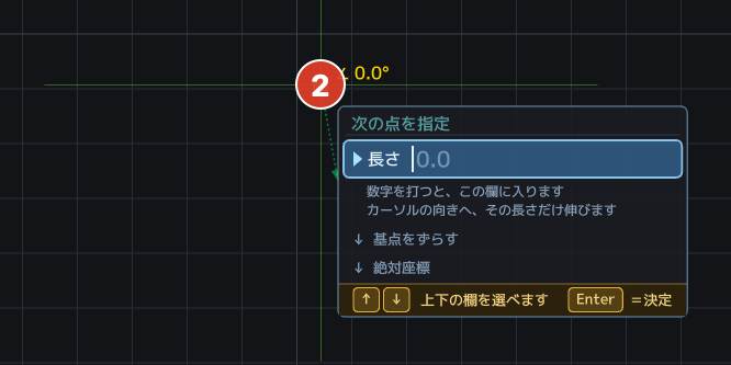
② - ③Click the second point (@1000,0, or a direction plus a number, work too).
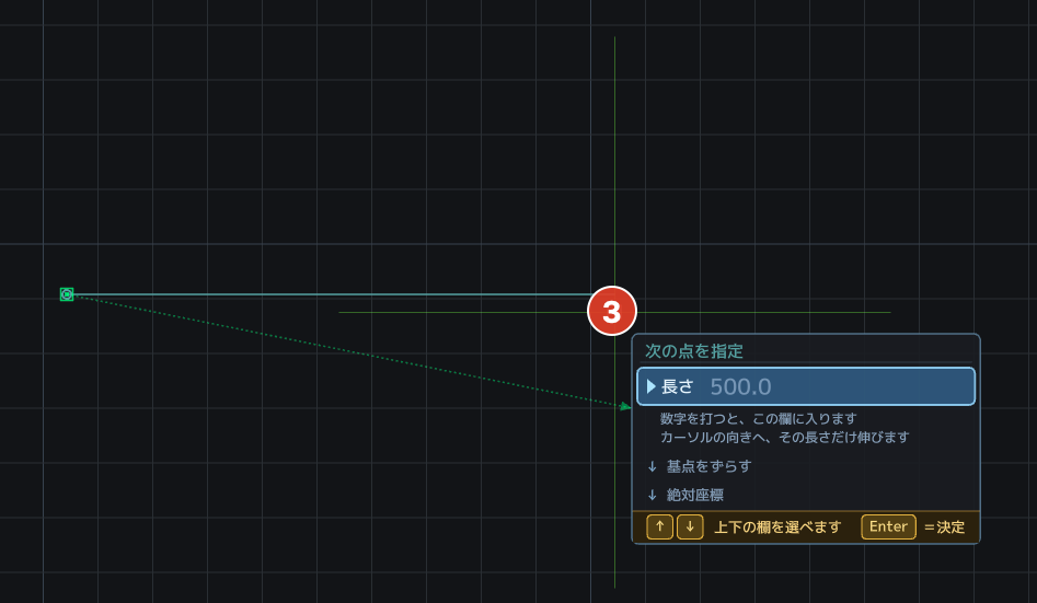
③ - ④It carries straight on. Press Esc when you are done.
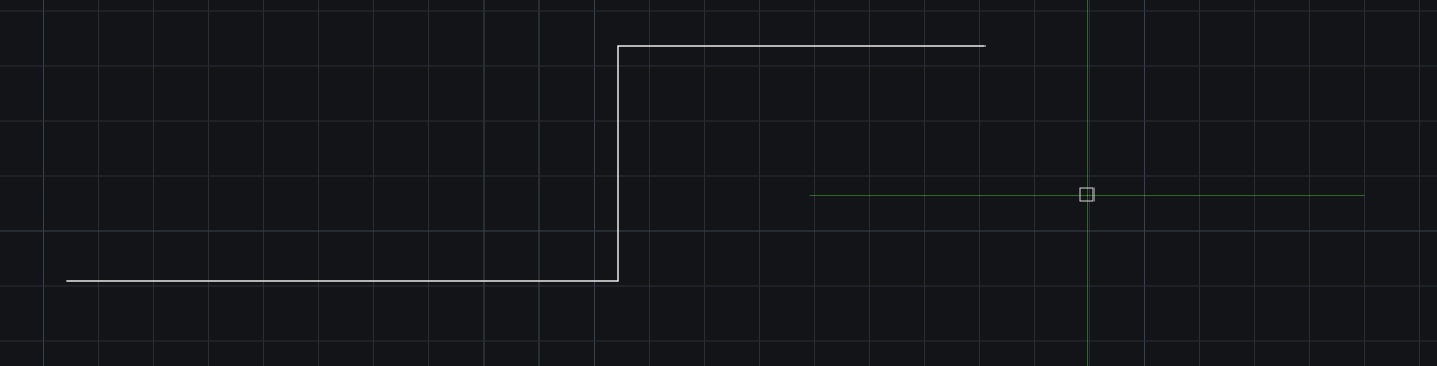
④
PL / PLINE (polyline)
- ①Press ポリライン (Polyline) on the ribbon, or type PL → Enter.
- ②Click the first point → the next → the next… (numbers work just as they do for a line).
- ③Right-click or Enter finishes it = at that moment it becomes one single object. U takes back one vertex at a time. Esc throws away what you were drawing.
閉じたポリラインにする】(3D の押し出しで立体になるのは、閉じた形です)
- 描いている途中で C を押す=最後の点から始点へ辺を足して閉じます。小窓に C(または 閉じる)と打っても同じです。
- 始点をクリックしても閉じます。描いている途中の点にも吸い付くので、始点に「端点」の印が出たらクリック=そのまま閉じた形になります。
- 閉じるには頂点が3つ以上要ります(2つでは往復の線にしかなりません)。
- The only difference from a line is whether it is one object. Lines are born separately, one per stroke; a polyline gathers into one when you finish.
- Use it for outlines, site boundaries, pipe runs — anything you will later want to select whole.
- Polylines from other CAD programs open as one object and are saved back as one object.
- トリムでは、ポリラインをそのまま切れます(一本のまま)。閉じたポリラインを切ると、開いた一本になります。ふくらみ(円弧の辺)も、途中で切れば正しく分かれます。自分と交わった所でも切れます(行き過ぎた尻尾を落とせます)。切った両端がぴったり出会ったら、閉じたポリラインになります。
- It can also be chosen as a cutting edge (the thing you trim back to, or extend up to).
- フィレット・面取りは、ポリラインの角に効きます(十五期百三十九号)。隣り合う二つの辺をクリックすると、その間の角が丸く(斜めに)なります。※弧を別に産まないので、一本のままです。他所のCADでも一体で開きます。
- Offset (O) fattens a polyline whole, in parallel.
- Divide (DIV) spaces points by equal arc length along the whole run. A closed shape gets exactly count points; an open one gets count-1, with none at the two ends.
C / CIRCLE
- ①Type C → Enter. Click the centre.
- ③Click a point the circumference passes through. To set the radius by number, type 4000, R2000 or D8000 (diameter) in the Command Line.
A / ARC (three-point arc)
- ①Press 円弧 (Arc) on the ribbon, or type A → Enter.
- ②Click three times: start point → a point the arc passes through → end point. From the third point on, the arc follows your cursor. Esc goes back one step = if you are unsure of the end point you can place the through point again.
- Snapping works on endpoints and intersections, so connecting arcs land exactly.
- When tracing a PDF underlay, three taps along the curve are all it takes.
EL / ELLIPSE
- ①Press 楕円 (Ellipse) on the ribbon, or type EL → Enter.
- ②Click three times: the end of one axis → the other end of that axis → the half-width of the other axis. From the third point on, the ellipse follows your cursor. Esc and right-click each go back one step.
- Take the third point longer than the axis and that becomes the major axis, standing upright (the longer one is automatically the major axis — the same rule as the original).
- It is saved as a DXF ELLIPSE just as it is, so it opens as an ellipse in other CAD programs.
SPL / SPLINE — a free curve
- ①Press スプライン (Spline) on the ribbon, or type SPL → Enter.
- ②Click, one after another, the points the curve should pass through (three or more). A smooth curve follows your cursor as you go.
- ③Right-click or Enter finishes it = one single curve. U = take back one point / Esc = throw away what you were drawing (the same as PL).
- The curve passes exactly through every point you clicked (the way a French curve is used).
- The points you clicked (the fit points) can be caught with snap afterwards. Grid lines or other lines can be brought exactly onto them.
- Use it for site contours, road alignments, decorative curves.
- It is saved as a DXF SPLINE just as it is, so it opens as one curve elsewhere, and the fit points travel with it, so it can be edited there as it is.
REC / rectangle
- ①Type REC → Enter. First point → click the opposite corner. To set it by size, give 700,700 (width,height) instead of the second point.
- REC C 10 = a rectangle chamfered 10 / REC F 15 = corners rounded R15. Type 0 to clear it.
- A rectangle is one whole polyline. Click any edge and the whole rectangle is selected (one-click selection). The four corners and the four edge midpoints all still snap, exactly as before. Offset (O) offsets the whole rectangle in parallel; Divide (DIV) divides the perimeter into equal parts. On the day you want just one edge, use X (explode).
POL / POLYGON (regular polygon)
- ①Press ポリゴン (Polygon) on the ribbon, or type POL → Enter. POL 6 = a hexagon (you can settle the number of sides first).
- ②Click the centre. Click the point on the radius (a number + Enter also works).
- While you draw, a bar appears at the bottom of the screen. You can choose the number of sides there (3 4 5 6 8 10 12) and whether it is inscribed or circumscribed. ← → also step the number of sides up and down.
- Inscribed = the corners sit on the circle (the radius runs from the centre to a corner).
- 外接=辺が円に接する(半径は中心から辺まで)。※六角ボルト・ナットの「二面幅」は外接です。二面幅24のナットなら、外接で半径12。内接で12を打つと、ひと回り小さい別の部品になります。
- What is born is one closed polyline (the same as a rectangle). It selects in one click, and hatch and offset work on it as they are.
- Its orientation is decided by where you take the radius point (aim straight up and a vertex points up, and so on).
GRID / structural grid lines
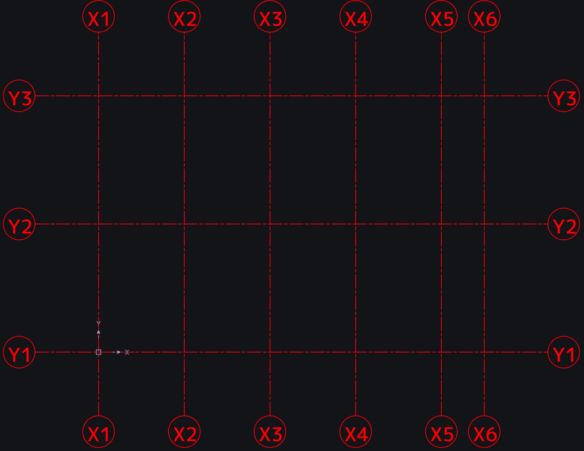
- ①Press 通り芯 (Grid) on the ribbon, or type GRID → Enter.

① - ②下の帯で、ピッチと本数を決めます。Xピッチ 1820・X本数 6 =1820の間隔で、芯が6本(列の数)。Yピッチ・Y本数も同じ書き方です。ピッチ欄には「1820*4, 910」と並びも打てます(不等ピッチ)。=910 や 455 が混じる実務の芯は、こちらで。

② - ③置く場所をクリック。スナップが効くので、図枠の角にもぴたりと置けます。原点(0,0)に置くなら【原点に置く】を押します。

③
打つそばから、格子のゴーストが育ちます(置く前に姿が見えます)。【符号 紙mm】=符号の丸(X1・Y1)の直径。紙のmmで打ちます(JIS A 0150 は 9mm)。図面ではページ設定の縮尺の分母倍になります(1:100 なら直径 900)。※狭いピッチ(910 など)で符号が重なる日は、ここを小さくします。=全部の符号が同じ大きさのまま、きれいに収まります。【延長】=芯を建物の外へ伸ばす長さ(図面の単位)。0 か 空Enter で自動(丸の半径×4)に戻ります。
W / 壁
- ①リボン「壁」か、小窓に W →Enter。距離は小窓に W 100,100(=厚200)。W 0,150 =クリックした線の位置に一本+150(0=スナップ点そのもの)。
- ②点を順にクリックします(線分やポリラインと同じ呼吸です)。二点で終わりにするなら、そこで右クリックか Enter=一本の壁になります。三点、四点と続ければ、曲がり角は自動で継がれます(面がつながります)。
- ③右クリックか Enter で置く。Esc=打ちかけを捨てる/U=置いた壁を戻す。
- F8=直交(水平・垂直だけ)。極トラも効きます。
- 数字+Enter でも打てます(「通り芯から2000」がそのまま言えます)。
- 柱(閉じたポリライン・円)を貫くと、柱の中で切れます(柱残しの術)。
- 鋭すぎる角は、継がずに角を落とします(細い針が伸びるのを避けるため)。
WW / 柱まわし=柱を順にクリックすると、壁が回る
- ①リボン「柱まわし」か、小窓に WW →Enter。
- ②下の帯で決めます。【厚】150 のように打ちます(式も打てます)。【外面合わせ/センター/内面合わせ】=壁をどこに置くか。外周の壁は柱の外面にツラ、内部の壁は芯のセンター、が現場の普通です。【一体化/柱残し】=柱の輪郭も溶かして一本の外形にするか、柱を残すか。
- ③柱を順にクリック。柱の中ならどこでも構いません(角を狙わなくてよい)。柱でない所を押すと、吸着した点が芯の角になります(柱の無い角はそこで曲がる)。
- ④最初の柱へ戻ると、一周して置きます。途中で終えるなら右クリックか Enter。開いたまま置くときは「進む向きの左」を内側と見ます。逆なら逆順に。
- 角も丁字も自動で繋ぎます。開口部は、そこだけ避けて打ってください。
- U=打った柱を一つ戻す/Esc=打ちかけを捨てる。置いた後は U ひと押しで丸ごと戻ります。
DT (single-line text): placing one line of text with a box
- ①Type DT → Enter (DT 5 = start at text height 5, DT 右下 = specify the justification). The 【文字】 (Text) button in the 作成 (Create) group does the same.
- ②Take the box the text will sit in with two opposite corners (the height of the box becomes the text height; the corners can be taken exactly with snap). 🔑 Draw a rectangle first, select it, then press DT = that rectangle becomes the box (and the rectangle stays). 🔑 Inside a table cell or a title block, use 【枠の中をクリック】 (click inside the box) on the bar = one press and it becomes the box.
- ③Type your line on the spot and press Enter to accept (the ✓ button, or a click outside the box, do the same). Esc = cancel. There is no line break here (for notes with line breaks, use MT).
- ④The text attaches to the box exactly as the justification says (【右下】 bottom-right puts it at the bottom-right of the box, 【中央】 centre puts it dead centre).
The justification (the nine squares) can be changed at any time
- Press one of the nine squares on the bar below the box and it changes even while you are typing. The half-typed text moves inside the box before your eyes (what you are shown is what you get).
- The text height can also be corrected at any time in the field on the bar (expressions work too: 7*2).
- 🔑 The height field is in paper mm from the start (one of the two choices on the bar; it is the default). Type 3.5 and on a 1:50 drawing it is placed as 175, and prints at 3.5 mm on paper. Multiplying by the scale is the tool's job. The bar shows the result: “=図面では 175(1:50)” (= 175 on the drawing). This is a translation at the moment you type; the text you placed stays at 175 (the tool does not touch a size a person has decided). Change the scale later and the text stays 175 = if you want text that follows the paper instead, switch its 大きさ (size) to 【紙のmm】 in Properties (PR), for the selected text only. To type in drawing units as before, press 【図面の単位】 on the bar.
- Text you have placed can be retyped by double-clicking it (rotated text keeps its angle).
Fonts: standard, light, bold, or the engraving typeface
- The Linetype / Dimension / Text bar (just under the ribbon) always carries a 【書体】 (Font) field, run the same way as the layer field. Press ▼ and a list drops down, each name drawn in its own face. Choose one and the text you type from now on uses it.
- Select text you have already placed and then choose from the list, and that text changes font (any number at once; U undoes it). The field turns pale blue to announce the font of the selected text. It is also shown on the 書体 (Font) row of the Properties panel; press it to move to the next font.
- Press the 【書体】 field on the bar and it cycles through the shelf one by one (it changes even while you are typing).
- The 文字の書体 (Text font) row in the Page Setup panel also lets you press a name and choose (again, each drawn in its own face).
- In the Command Line: 書体 機械彫刻 (or FONT kikai in English letters). 書体 ? lists what is on the shelf.
- 機械彫刻 (kikai) = a face reproducing the standard 1970s Japanese engraving-machine lettering (f.k Kikai Chokoku, by Kim). It has no φ, ±, ⌒ or ∠ and lacks some kanji, so those characters alone appear in the standard face.
- BIZ UDGothic and BIZ UDMincho (Morisawa, OFL) are included as well (Mac and Windows; they are not carried in the web version).
- The usual faces on this machine also appear under ▼ (Mac = Hiragino Kaku Gothic, Hiragino Mincho / Windows = MS Gothic, MS Mincho, Meiryo, Yu Gothic). Faces your machine does not have do not appear.
- Fonts named by drawings from elsewhere (MS ゴシック, Arial and so on) are drawn in that face if this machine has it, and substituted with the standard face if not (the same convention as the original's font substitution). ※ The web version has only the fonts shipped with it.
- To use your own font, press “+ 書体を足す…” (Add a font…) at the foot of the ▼ list, put a TTF or OTF into the 書体 folder that opens, and restart K'Ad (it then appears under ▼; in the Command Line, 書体 filename).
- The font you chose is saved as the drawing's text style (STYLE) = it opens under the same font name in other CAD programs.
MT (multiline text): pouring a note with line breaks into a box
- ①小窓に MT →Enter(MT 5=はじめから字高5)。リボン「作成」の【段落】ボタンでも同じです。🔑四角を先に描いてあるなら、それを選んでから MT=その四角が、そのまま枠になります。(`REC 590,300` と数字で描けば、枠を正確に決められます)※選んだ四角はそのまま残ります(枠として借りただけ)。図枠や表の罫線を枠に使っても、線は一本も消えません。🔑表のセルや図枠の中に書くなら、帯の【枠の中をクリック】へ(Tabでも)。その部屋を一回押すだけで、囲まれた範囲がそのまま枠になります。(表の罫線は通し線なので、セルは「図形」としては選べません。だから部屋のほうを指します)
- ②文章の入る枠を、対角の2点でクリック。※枠から取るのは幅だけです(=折り返しの幅)。縦は文章が増えれば下へ育ちます。字高は枠の高さでは決まりません。帯の【字高】の欄の値(はじめは 3.5)で打ち始めます。枠が決まると、帯に【幅】と【字高】の欄が並びます。どちらも押してその場で打ち替えられます。
- ③Type your text into the box. · Enter = a line break (it means something different from Enter in single-line text) · Pressing ↓ on the very last line also breaks the line · Characters that run past the width wrap automatically as you type (you see them wrapping exactly as they will once placed)
- ④直したい所は、ワードと同じように選べます。・枠の中をクリック=そこにカーソルが移ります・押したまま引く=反転(青くなった分が「選んだ分」)・Shift+矢印・Home・End でも、反転を伸ばせます・Ctrl+A(Macは⌘A)=本文をぜんぶ反転・反転したまま打てば置き換え、BackSpace/Delete でその分だけ消えます※引いている途中で枠の外へ出ても、反転は続きます(戻ってくれば繋がります)。
- ⑤選んだ字は、コピー・切り取り・貼り付けができます(ワードと同じ指)。・Ctrl+C(Macは⌘C)=コピー/Ctrl+X=切り取り/Ctrl+V=貼り付け・メモ帳・表計算・他所のCADからも、そのまま貼れます・反転したまま貼れば置き換え、何も選んでいなければカーソルの所へ入ります※一行の文字(DT)に、改行の入った文章を貼ると、改行は空白ひとつになります(一行の器なので。落として詰めると、次の行が前の行の尻に生えます)。※貼った字は、いま帯で灯っている飾りを着ます(打った字と同じ扱い)。飾りそのものは持ち回りません=クリップボードは、素の字だけを運びます。
- ⑥飾り(太字・斜体・下線・上線・取り消し線)は、枠の下の帯で。・反転してから押す=その分に掛かります(もう一度押すと外れます)・何も選ばずに押す=これから打つ字に掛かります(ワードと同じ)・太字は Ctrl+B、斜体は Ctrl+I、下線は Ctrl+U(Macは⌘B・⌘I・⌘U)でも。灯っているのが、いまの状態です※太字は、他所のCADでは太くならないことがあります(DXFは書体の名前で太字を表す決まりで、うちは書体名を勝手に足さないことを選びました)。・斜体は、字を15度たおして描きます(字送りは変わりません)・取り消し線は、訂正・削除の印に使います※飾りはDXFの決まりどおりに保存されるので、他所のCADでもそのまま出ます。
- ⑦字の大きさは、帯の右の【字高】の欄で、その場で変えられます。・欄の単位は既定で【紙のmm】(DTと同じ・帯の二択で【図面の単位】にも)。・押すと今の値が入って開きます(続きから直せます)・式も打てます(例:40/2 → 20)。Enter で決定、Esc で中止※変えると折り返しも一緒に変わります(枠の横幅は変わりません)。
- ⑧文章を、枠のどの隅に合わせるかは、帯の右の【基準】の九マスで。・押した点に、文章のその隅が来ます(左上・中央・右下…の九通り)・中央を選べば、表のマスのど真ん中に収まります・下を選べば、文章は上へ育ちます(上なら下へ、中なら上下へ)※既定は【左上】です。打っている最中に、いつでも変えられます。※打ち直しのときは出ません(そのときの隅を、そのまま守ります)。
- ⑨There are three ways to finish. They all do the same thing. · Press 【✓ 確定】 (accept) below the box · Ctrl+Enter (⌘+Enter on Mac) · Click outside the box To give up, press Esc (right-click does the same).
- ⑩置いたあとでも、打ち直せます。・段落をダブルクリック=そのまま枠が開いて、続きから直せます・選んで小窓に DDEDIT(または ED)でも同じです・右クリックの献立の【文字を編集】でも開きます・直したら、新しく打つときと同じ終わり方(✓・Ctrl+Enter・枠の外)・Esc なら、元のままで閉じます※空にして確定はできません(元のまま残ります)。消すときは選んで Delete。※傾いている段落は、まだ開けません(Xで分解すると行ごとの文字になります)。
Choosing between multiline text and ordinary text (DT)
- A single line — a symbol, a number, a note beside a dimension → DT
- A note of several lines, a specification, a legend → MT With MT, change the width later and the wrapping follows.
Multiline text that came from another drawing
- A single block of note text containing line breaks (MTEXT) from another CAD program opens as one block, and is given back as one block when you save. The font and height it names are not used here, but we hold them for you and return them.
- The wrapping width is held too, so it wraps in the same places as it did in the other program.
- Touch it and it announces itself as “段落文字 3行” (multiline text, 3 lines). Touch any line and the whole is caught (move, copy and rotate all work as they are).
- The text size can be changed (select it, right-click → text height).
- 打ち直せます(ダブルクリック)。書体の指定など、うちが使わない飾りもそのままお返しするので、直しても図面は痩せません。※ただし、うちがまだ扱えない飾り(色・字高の倍率など)が入っている段落は、開かずに、その場で理由を言います——直すとその飾りが失われるからです。その場合は X(分解)で行ごとの文字に分ければ、一行ずつ打ち直せます(※分解すると、書体・字高の指定は失われます)。※傾いている段落と、貼り付ける隅が左上でない段落も、まだ開けません。
LE / leader
- ①Type LE → Enter.
- ②Click the tip of the arrow (it snaps to the hole or corner you want to point at).
- ③Click the elbow (the line lands horizontally from there).
- ④Give the text height with one more point (move left or right and the side the words come out on swaps; Enter = the previous height).
- ⑤Type the words and press Enter.
H / HATCH
- ①Type H → Enter (the ハッチ (Hatch) button on the ribbon does the same).
- ②Click once inside the area you want filled. That alone sets the machine looking for the shape that encloses that place, and fills it. If circles or rectangles float inside it, they are left out as islands.
- Shapes with rounded or chamfered corners, rooms made of crossing lines, rough sketches with corners still overshooting — all of them fill with one click inside.
- It searches only the part visible on the screen. Bring the area you want filled into view before you press.
◆ When the shape is not closed (there is a gap, or the lines do not meet), it says 囲まれていません (not enclosed) and the point you pressed becomes the first point. Carry on with 【click the corners in order → Enter】 to enclose it and fill (snapping works; right-click takes back one point). Over a sketch, or where lines are missing, this way is the sure one.
- The pattern is chosen on the bar that appears at the very bottom of the screen. Nine samples sit there; just press one. ← → step through them as well. The moment you press, the preview of the area you are enclosing takes on that pattern = you can compare them on the drawing itself, before filling. (The bar appears only during the hatch command and withdraws when you finish.)
- H ? also lists what is available (and H ANSI37 names one directly).
- The fineness of the pattern (the pitch) is set with 【ピッチ】 on the bar. The default is 【自動】 (automatic) = the scale denominator becomes the multiplier directly (the patterns are defined in paper mm, so 1:20 means ×20 to give the paper look. It announces “=紙で 12.7mm” — 12.7 mm on paper). Type a number to set it by hand (expressions work). A hatch takes the value in force when you place it, and does not move if you change the scale later.
- From the Command Line: H ANSI31 20 = hatching at a multiplier of 20 (raise the number and the pattern opens out).
- If it says the pattern would draw no lines, or too many and it stopped, correct the multiplier (the history says how many lines).
Construction symbols: beam, column, footing, mat slab, level, section arrow, drawing title
The symbols familiar from construction drawings can be typed and placed on the spot.
There are three ways in: 【記号】 (Symbol) in the 作成 (Create) group / 記号 in the Command Line / the flick shelf.
- ①A bar appears at the very bottom of the screen. From the left: beam tag, column tag, footing tag, mat-slab tag, level mark, section arrow, drawing-title box. Each shows a sample, so press to choose.
- ②【紙の字高】と【縮尺】を、帯の欄で決めます。縮尺の既定は【ページ設定】の縮尺です(自動なら紙に収まる縮尺・指名ならその値)。破線・寸法・ハッチと同じ一つの縮尺を読みます=直す場所は一つ。道具に入ったとき、履歴が「ページ設定の縮尺に合わせました」と名乗ります。違えば、ページ設定の縮尺を直すと、破線も寸法もハッチも記号も一度に合います。この図面だけ別の縮尺で置きたいときは、帯の欄か 記号 1:50 で。紙の上(レイアウト)では常に 1:1 です。※PDFから取り込んだ図面(1単位=紙の1mm)は、ページ設定で 1:1 を指名してください。・大きさが合わなければ、置いてから【拡大縮小(SC)】でも直せます。記号は楕円・線・文字なので、ふつうの図形と同じように扱えます。記号は「紙の上で何ミリか」で決まります(JISの常用は 3.5)。図面は実寸なので、1:50 の図面なら 50倍にして置きます。帯には掛け算の答え(=図面で 175)も出ます。※ここが合っていないと、記号だけが極端に大きく/小さくなります。
- ③Click where it goes. Snapping works, so it drops exactly onto a grid intersection.
- ④Type it there and then. Tab = the next field / Shift+Tab = the previous / ↑↓ = the field above or below. As you type, the ellipse or the box grows to fit what is in it.
- ⑤✓ or Ctrl(⌘)+Enter accepts. Esc = cancel (the drawing is unchanged). After placing, you can carry straight on = click the next place. Finish with a right-click or Esc.
What each one looks like, and the fields you fill
- Beam tag = an ellipse divided into three by two lines. Five fields: top of the foundation beam (outside the tag, above) / top of concrete / beam mark / beam width * depth (formwork size) / added thickness (outside the tag, below).
- Footing tag = the footing mark on the left, and two rows on the right (bottom of footing / footing thickness).
- Mat-slab tag = a rectangle divided into three by two lines (top level / mark / thickness).
- Column tag = a rectangular box with three rows (column mark / section / reinforcement). No dividing lines.
- Level mark = a ▽ with a horizontal line. The apex of the ▽ is the position of that level itself.
- Section arrow = the mark (A, B) + the arrow + the right-angled end of the cutting line. The shape was built by measuring a real drawing. Draw the cutting line itself with a line (L) = its length differs from drawing to drawing, so the symbol does not carry it.
- Drawing-title box = a rectangle with the drawing name.
- A symbol you place becomes ellipses, lines and text. No special “symbol” object lives in the drawing = move, rotate, scale, trim and changing layers all work on it exactly as usual. It opens as it is in other CAD programs too.
- One press of U removes a whole symbol at once.
- For the section arrow, the direction of view and the head are chosen on the bar below.
◇ Direction of view = four (up, right, down, left) Choose the section arrow and four arrow pictures appear on the bar below. Just press one. · The way the arrowhead points = the direction you look at the drawing · The end of the cutting line folds 90° clockwise from that direction · The mark (A, B) stays upright whichever direction you choose = because that is how real drawings do it. To cut on a slant, place it and then turn it with Rotate (RO). ◇ Head (the arrowhead) = three · Single barb = the shape measured from a real construction drawing (the default). The axis of the cutting line serves as one side of the head. · Open arrow = a slim symmetrical triangle. · Hollow triangle = a stubby triangle (the same apex angle as the arrow on a real leader). None of them is “the correct one” — the drafting standards do not go as far as prescribing the shape of the arrow on a cutting line (JIS A 0150 and JIS Z 8316 both require the arrow, but neither prescribes its shape). Choose to match the practice of your office and your drawing.
- From the Command Line you can name the type, the scale, the paper text height and the arrow direction directly: 記号 梁 / 記号 1:50 / 記号 3.5 / 記号 左.
- The grid bubbles (the circles marked X1, Y1) are not placed from this bar; the grid command (GRID) raises them together with the lines (the circles are 9 mm across on paper = decided by the Page Setup scale).
分野を「機械」へ=幾何公差と三角法の記号
帯の左端【分野】の ▲ ▼(または ↑ ↓)で、建築/機械/電気/設備を行き来します。
その分野の中の記号は、【記号】の ◀ ▶(または ← →)で前後へ送れます。※縦が分野・横が記号=頭の中にツリーが描けるように、指の向きを揃えてあります。(もちろん、記号のカードを直接押しても選べます)
機械の棚には、いま二つの家族が住んでいます。
- 幾何公差の記入枠(JIS B 0021)=14種。真直度・平面度・真円度・円筒度・線の輪郭度・面の輪郭度・平行度・直角度・傾斜度・位置度・同軸度・対称度・円周振れ・全振れ。枠は共通(記号|公差値|データム)で、違うのは記号の絵だけ。形状公差の四つ(真直・平面・真円・円筒)はデータムを持たないので、その升は出ません。枠の高さ=字高の2倍・記号の升は正方形(規格の作法)。記号の絵は線と円で描くので書体に頼らず、どの机でも同じ顔で出ます。
- 三角法の投影記号(JIS Z 8316/ISO 5456-2)=第三角法と第一角法の二つ。円錐台を正面から見た台形と、小さい端から見た二重円の絵です。・第三角法(日本の主流)=左に二重円、右に台形(短い辺が円の側)・第一角法(欧州の主流)=左に台形(短い辺が外側)、右に二重円大きさは【紙の字高】=小さい円の直径(3.5 なら大円 7mm・記号の高さ 7mm)。打つ欄はありません=置く場所をクリックして、✓ か Enter で置きます。表題欄の所定の位置に置く記号です(矢示法で描いた図面では要りません)。
- 小窓からは 記号 第三/記号 第一/記号 三角法/記号 真直度 のように名指しできます。
分野を「電気」へ=配線用の図記号(住宅の内装)
間取りに描く電気の記号です(JIS C 0303 構内電気設備の配線用図記号)。
※回路図の記号(JIS C 0617)とは別の規格です。あちらは制御盤の中身の図です。
いま九種が住んでいます:コンセント/点滅器(スイッチ)/照明(白熱灯)/シーリング/ダウンライト/蛍光灯/換気扇/分電盤/ルームエアコン。
- 大きさは【紙の字高】=丸の直径(3.5 なら紙で 3.5mm の丸)。三角法の記号と同じ物差しです=家の中で二度覚えなくて済みます。
- 傍記(記号の右に書く小さな字)は、要るときだけ打ちます。空のままでも置けます——規格が「15A 125V は傍記しない」と決めているからです。コンセント … 2(2口)/E(接地極付)/ET(接地端子付)/WP(防雨形)/20A点滅器 … 3(3路)/4(4路)/2P(2極)/P(プル)/L(確認表示灯)照明 … 100(ワット)/蛍光灯なら F40 のように
- 塗りつぶし(コンセントの上半分・点滅器の丸・分電盤の三角)は、ハッチの「塗りつぶし」として置かれます=拡大しても縁は本物の円のままです。※コンセントを上半分だけ塗るのは、規格が「壁側を塗る」と決めているためです。
- 小窓からは 記号 コンセント/記号 点滅器/記号 分電盤 のように名指しできます。
分野を「設備」へ=給排水・衛生の図記号
配管の弁と、排水の桝です(国土交通省の公共建築設備工事標準図に合わせています)。
※設備には、電気の JIS C 0303 に当たる一つの規格がありません。実務ではこの標準図と、空気調和・衛生工学会の図記号が共通語として使われています。
いま十二種が住んでいます:弁 … 仕切弁(GV)/バタフライ弁(BV)/玉形弁(SV)/逆止弁(CV)/ボール弁(BAV)/コック(CK)/埋設弁桝 … トラップ桝(T)/インバート桝/ため桝/公共桝(公)/グリース阻集器(GT)
- 弁の四つ(GV・BV・SV・BAV)は、形がまったく同じ蝶(ちょう)です。見分けるのは右上の符号だけ——これは標準図がそう決めているからで、符号は記号の一部として最初から入っています(打つ必要はありません)。
- 傍記(呼び径など。例 20A や 50×25)は、要るときだけ打ちます。空でも置けます。
- 記号は単独で置きます。前後に伸びる管の線は含みません(置く場所には、もう管が引いてあるはずなので)。
- 小窓からは 記号 仕切弁/記号 ため桝 のほか、図面で読んでいる符号のままGV・BV・SV・CV・BAV・CK・GT でも呼べます(日本語入力を切らずに打てます)。